Overview
Planning Mode allows you to:- Design multi-step processing workflows as a directed acyclic graph (DAG)
- Chain together module executions, human review tasks, JavaScript routing scripts, and AI agents
- Define dependencies between steps, including action-qualified edges (e.g., proceed only if “Approve” was clicked)
- Visualize the workflow as an interactive flow diagram
- Monitor execution progress with automatic deadlock detection
The Flow Editor
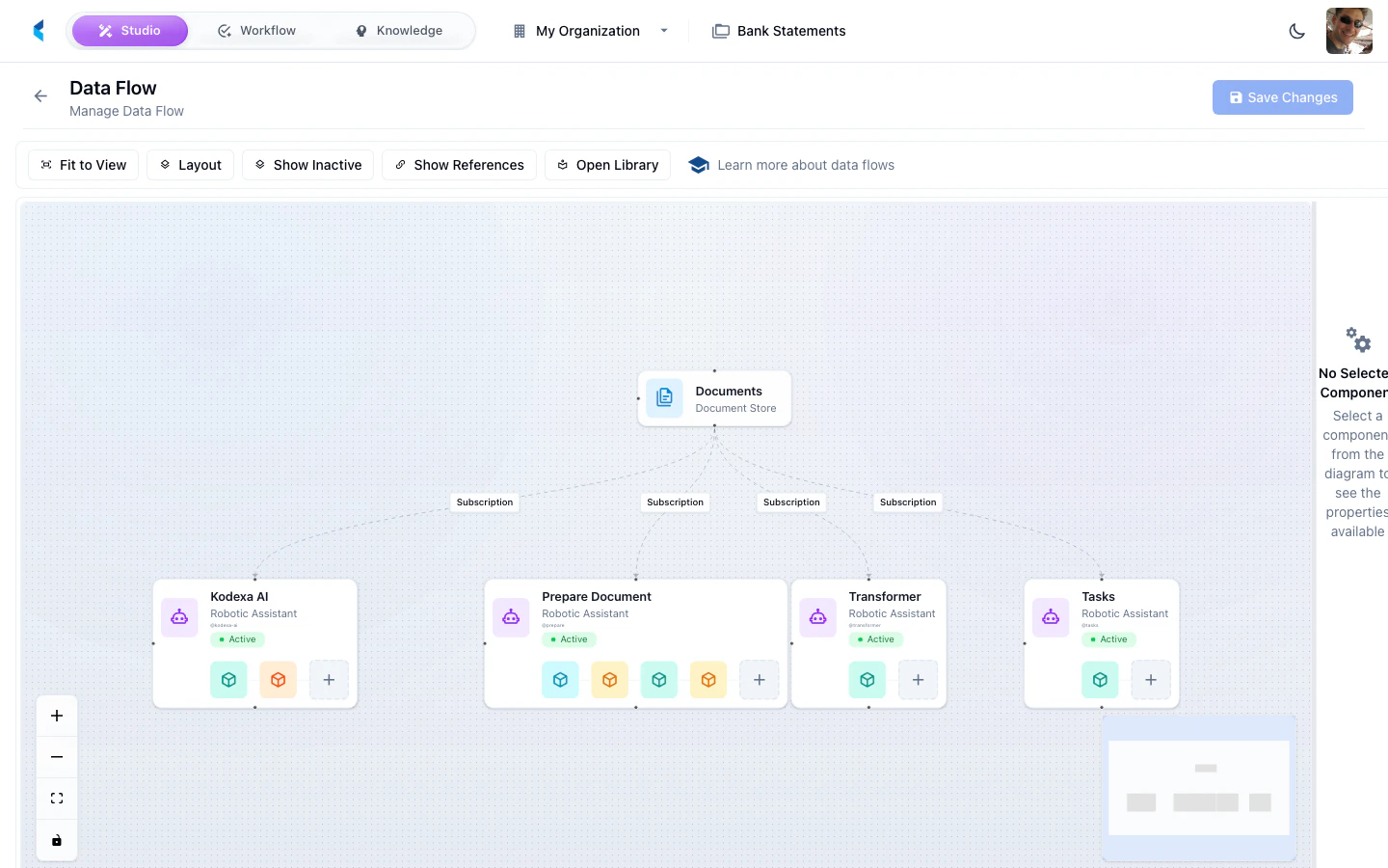
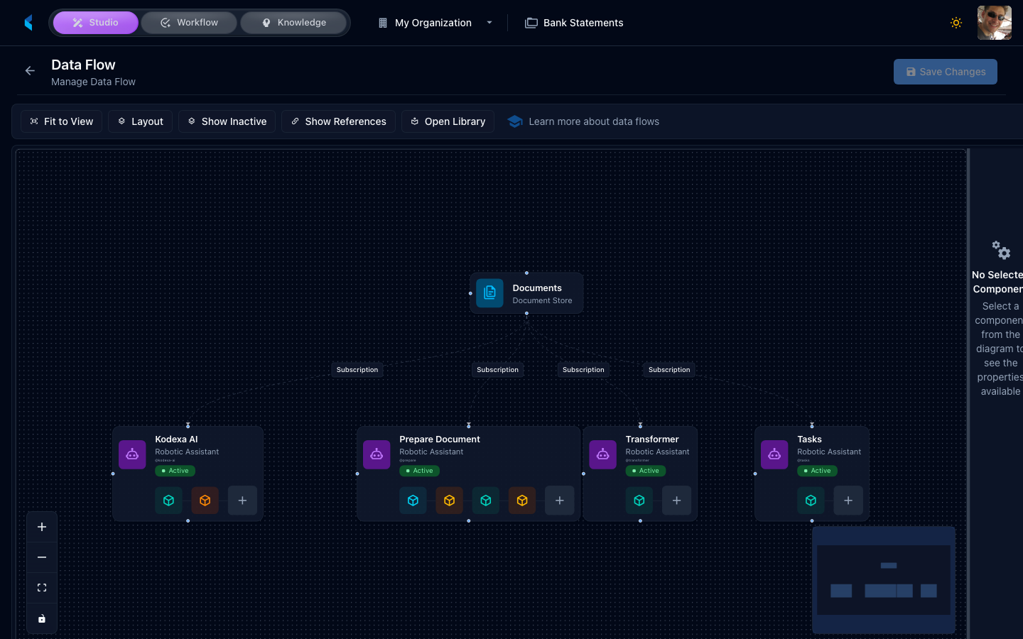
The visual flow editor provides a drag-and-drop interface for designing workflows:- Left panel — Node palette with available step types. Drag nodes onto the canvas to add them.
- Center — Interactive canvas showing nodes and edges. Draw connections between nodes to set dependencies.
- Right panel — Properties panel for the selected node. Configure step-specific settings here.
Double-click a node to zoom and center it. Use the mini-map in the corner for navigation in large workflows.
Plan Node Types
Each step in a plan is a planned item with a specific type. The platform supports the following node types:EXECUTION
Runs a module (such as a parser, extractor, or classifier) on the task’s documents.CREATE_TASK
Creates a sub-task assigned to a human reviewer. The plan pauses at this step until the reviewer completes the task by clicking an action button. (Older plans may useTASK as the type value; the materialiser canonicalises it to CREATE_TASK at activity start. Author new steps with CREATE_TASK.)
Sub-task templates used in plans are typically marked with
subTaskOnly: true so they do not appear in the main task creation dialog.
SCRIPT
Runs inline JavaScript to make routing decisions, inspect documents, modify content, or assign knowledge features. Scripts return an action name that determines which downstream dependency edge to follow, enabling conditional branching.
The script has access to the task context, document families, knowledge features, and can load and modify KDDB documents. Downstream steps can depend on a specific action outcome.
Script Steps Guide
See the full Script Steps guide for the complete API reference, document modification examples, knowledge feature assignment, and ready-to-use code snippets.
AGENT
Spawns an AI agent to process the task’s documents autonomously. The agent uses configured modules as tools and follows a prompt to decide how to process the documents.LLM
Runs a bounded prompt as a first-class step. The model response can be mapped into step output for downstream consumption, and the step can emit named actions for routing. (Older plans may useAI_PLANNER or AI_PROMPT as the type value; the materialiser canonicalises both to LLM at activity start. The original “dynamically insert additional plan steps” behaviour those legacy types implied is no longer supported at runtime — LLM is a regular bounded prompt step.)
See the LLM Steps guide for the full LLM step reference.
Dependencies
Each plan step can declare dependencies on other steps using thedependsOn array. Dependencies control execution order — a step will not start until all its dependencies have completed.
Simple Dependencies
In the flow editor, draw an edge from one node to another to create a dependency. In YAML:Action-Qualified Dependencies
When a dependency is on aCREATE_TASK or SCRIPT step, you can qualify the dependency with a specific action. The downstream step only executes if the upstream step completed with that particular action.
This enables conditional branching — for example, routing to different processing steps based on whether a reviewer clicked “Approve” or “Reject”:
stepSlug:actionSlug — the token after the colon is the upstream action’s slug (declared on scriptActions[].slug, promptActions[].slug, or a CREATE_TASK template’s action slug). Older plans use a uuid value in that position; that is the legacy spelling of slug and still resolves, but new authoring should use slug. In the flow editor, when you connect from a CREATE_TASK or SCRIPT node that has multiple actions, each action appears as a separate connection handle at the bottom of the node. Draw edges from the specific action handle to create action-qualified dependencies.
Example Workflows
Simple Extraction Pipeline
A linear workflow that parses a document, extracts data, then creates a review task:Conditional Branching with Scripts
A workflow that classifies documents and routes them to different processing paths:Approval Workflow
A workflow with a human approval gate that branches based on the reviewer’s decision:DAG Flow Visualization
Plans are displayed as an interactive top-to-bottom flow diagram in the plan monitoring panel. Each node represents a planned item, and edges show dependencies (with action labels on qualified edges). Node colors indicate status:- Pending — Waiting for dependencies
- Running — Currently executing
- Completed — Finished successfully
- Failed — Encountered an error
- Deadlocked — Blocked by a failed dependency (see below)
Deadlock Detection
The platform automatically detects deadlocked plans. A deadlock occurs when:- A plan step fails, and
- Other pending steps depend on the failed step (directly or transitively)
Getting Started
1
Create a Task Template
Navigate to Task Templates and create or edit a template. On the Details tab, check Enable Planned Sub-Tasks.
2
Open the Flow Editor
Switch to the Planned tab. The visual flow editor appears with a node palette on the left.
3
Add Plan Steps
Drag nodes from the palette onto the canvas. Configure each node using the properties panel on the right.
4
Connect Dependencies
Draw edges between nodes to set execution order. For
CREATE_TASK and SCRIPT nodes with multiple actions, connect from specific action handles for conditional branching.5
Test the Workflow
Save the template, then create a task from it. The plan executes automatically, and you can monitor progress in the plan status panel.